|
SOLAR TRACKING BOILER | |

| HomeGreetingProductApplicationsContact..... |
| - |
| 공동제작 |
| 링크 Links |
| 소식지 News |
|
사회적기업 |
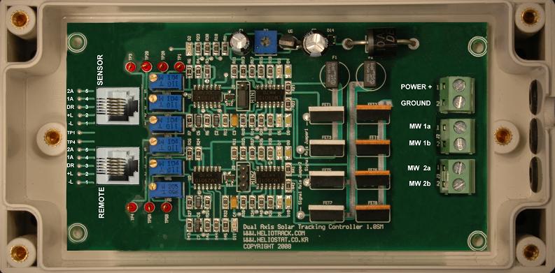
Heliostat Dual Axis Tracking Controller |
|
Specification |
Value |
Units |
|
Power supply |
12 ? 36 |
Volts DC |
|
Idle current drain |
.008 |
Amps |
|
Sensor (Comparator) Inputs |
0 ? 6 |
Volts DC |
|
Output voltage |
Equal to power supply |
Volts DC |
|
Continuous output current |
2.5 Amps @ 100% duty cycle |
Amps |
|
Pulsed output current (.1hz) |
5 Amps a@ 20% duty cycle |
Amps |
|
Pulsed output current (.1hz) |
20 Amps @ 5% duty cycle |
Amps |
|
Duty cycle (variable) |
0 ? 100 |
Percent |
|
Duty frequency (variable) |
.1 ? 60 |
Hz |
|
Duty cycle control voltage |
2.2 ? 4.5 |
Volts DC |
|
|
|
|
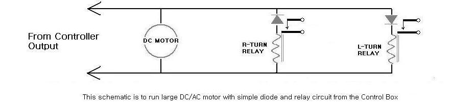
The dual axis tracking controller features three voltage comparator inputs and two solid state H-bridge driver outputs. Input 1 & 2 are window comparators for bi-directional control functions and input 3 is a single ended comparator whose output can be linked to the output of either direction of either window comparator, or to an input external unit for auxiliary control.
Although this controller is ideal for dual axis solar tracking it is also well suited for other control loads requiring moderate to high amperage DC power. Possible applications include, but are not limited to, recirculation pumps, relays, solenoids, fans, motion control, and system monitoring.
*** Caution***
High frequency duty cycles (greater than 5 Hz) can potentially damage the driver transistors before blowing a fuse. High frequency duty cycles should only be used with resistive loads of less than .5 amps and inductive loads of less than .2 amps. In every new configurations it is a good idea to monitor the temperature of the driver transistors to make sure that they are not overheating.
Controller circuit description
- Power: 12-36 VDC (volts direct current)
- Ground: Negative terminal of power supply
- Motor wire 1A: Usually wired to the East-West actuator - Positive when moving West
- Motor wire 1B: Usually wired to the East-West actuator - Positive when moving East
- Motor wire 2A: Usually wired to the East-West actuator - Positive when moving Down
- Motor wire 2B: Usually wired to the East-West actuator - Positive when moving UP
- Fuse 1: 3 amp slow blow fuse for East-West actuator
- Fuse 2: 3 amp slow blow fuse for UP-Down actuator
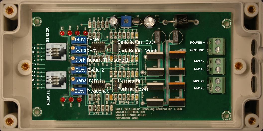
- Sensitivity 1: Turn counterclockwise to increase immunity of East-West channel if wandering is a problem
- Sensitivity 2: Turn counterclockwise to increase immunity of Up-Down channel if wandering is a problem
***Note: When the sun is partly obscured, optical solar trackers can be susceptible to wandering toward the brightest source of light, this could be a reflection from a window or the silver lining of a cloud. This circuit features a sensitivity adjustment that provides a way to compensate if wandering is a problem. The sensitivity can also be increased for applications requiring low-light tracking, or greater degrees of accuracy. Turning the adjustment screw clockwise will increase tracking sensitivity.
Dark return set jumper 1:
- Place jumper on {left and middle} pins to return EAST if the tracker is facing South (Northern Hemisphere)
- Place jumper on {right and middle} pins to return EAST if the tracker facing North (Southern Hemisphere)
- Remove jumper to disable return function.
Dark return set jumper 2:
- Place shorting jumper on {left and middle} pins to tilt Down at night
- Place shorting jumper on {right and middle} pins to tilt UP at night
- Remove jumper to disable return function.
Dark return threshold: Turn clockwise to set threshold to lighter. Adjust this if ambient light is keeping the tracker from returning at night. - - Duty cycle 1: Turn clockwise to increase duty cycle of East-West axis
- Duty cycle 2: Turn clockwise to increase duty cycle of Up-Down axis
- Duty Frequency: Turn Clockwise to INCREASE cycle time (Lower the frequency)
Sensor plug: This plug is connected in parallel with the remote control plug so they are interchangeable
Remote control plug: Pin 1 is the bottom pin when looking at the board as pictured
- Pin 1 : Ground
- Pin 2: 6 ? 6.2 VDC
- Pin 3: Dark return input
- Pin 4: East-West tracking input
- Pin 5: Up-Down tracking input
Connecting remote control pins will move the tracker as follows if the unit is facing South
- 1 & 5 Up
-- 2 & 5 Down
- 1 & 4 East
- 2 & 4 West
*** Never connect pins 1 & 2 together. This may damage the logic supply voltage regulator
****Before getting started there are two things that you must be aware of before working with the tracking controller.****
A) Never apply power directly to the motor leads when they are connected to the controller circuit. This will destroy the driver transistors and incur a $25 fix it fee. YOU MUST disconnect the motor wires from the tracking controller If you want to test your motors by connecting them directly to the power source.
B) Never reverse polarity of the supply power going to the controller circuit. This will blow the fuses and potentially damage the power transistors. This will also incur a $25 fix it fee.
A way to add reverse polarity protection has been built into the circuit board. This is done by cutting one trace and soldering a rectifying diode into pre-existing holes by the power terminal. Please contact us if you want your board modified in this way.
If you do damage the boards then remove the controller board from the plastic enclosure and send it back to us in a padded mailer. We will fix the board within two days and ship it back to you USPS priority. We will request a $25 payment via PayPal for the repair plus shipping.
Installation instructions
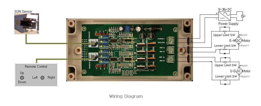
1) Mount the tracking controller box in an accessible location. Be sure to mount the box with the wires leading down, this will prevent water from running into the box. If you wish to drill holes in the controller box ? remove the 4 screws from cover, there is space on either side of the circuit board for mounting hardware to penetrate the plastic enclosure. When replacing the lid, be sure that the rubber grommet on the sun sensor cable is seated in the routed slot between the box and the lid. This will prevent water and insects from getting into the controller box.
2) Connect the motor wires from your actuators to the motor terminals on the circuit board.
Motor terminals 1a and 1b should control the EAST-WEST or AZIMUTH actuator.
Motor terminals 2a and 2b should control the UP-DOWN or ALTITUDE actuator.
In the Northern Hemisphere...
Motor wire 1a will be positive when the tracker needs to move West.
Motor wire 2a will be positive when the tracker needs to tilt UP. You may need to reverse the polarity of these wires in step 5 if either actuator moves in the wrong direction.
In the Southern Hemisphere the polarity of the motor wires will need to be reversed.
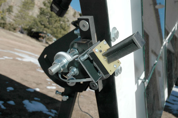
3) The sun sensor should be installed on your mechanical tracker, with the cable leading down (Tilt down direction). The sensor comes with floating spring mount for precise aiming. Remove the wing nuts and one washer from each mounting bolt (this leaves one washer and the spring on each bolt). Pass the three bolts through pre-drilled holes on your sensor bracket. Replace washer and then the wing nut on each bolt. This provides a spring-loaded tripod mount for your sensor. Fine-tune the alignment of the sensor simply by turning the wing nuts in the appropriate direction.
4) WITHOUT THE POWER ON, connect your 12 - 36 VDC power supply wires to the power terminals on the controller circuit board. When these wires are connected, turn on the power and the unit should start tracking the sun within 30 seconds.
***Be sure to wait for at least 30 seconds for the tracker to move before assuming there is a problem.
***The Red wire is +++ Positive +++ Take extra care not to wire the power to the tracker backwards, This will blow both fuses and possibly damage the driver transistors.
5) If an actuator is tracking in the wrong direction, turn off the power, reverse the polarity of the motor wires for that actuator, and turn the power back on.
6) Once you are satisfied that everything is working properly
replace the cover on the control box making sure that the routed notch in the lid goes around the stress grommet on the sun sensor wire. It is a good idea to put a bead of caulking around the lid before replacing it for long term outdoor use. This will prevent moisture from getting in.
***Maintenance note: Once a year place a coat of black fingernail polish around the base of the five photocells on the sun sensor to prevent water from penetrating and corroding the leads. Try not to get any fingernail polish on the top of the photocells. If you do, let it dry and then gently scrape it off with a wooden toothpick.